 The problem we worked on Sunday was the "voltage regulator". (In the voice of McCoy: "I am a computer programmer not a diesel mechanic!"). The engine is up front and it drives a Stamford generator. The only symtom we had was on the generator control panel was that the frequency (Hz) was at times bouncing all over the place (anywhere from 10 to 80Hz). I talk to Obie @ ESI that can service the Kubota and generator systems. The next question is: Does the generator also bounce around speeding up and down? Answer: no (it just runs happily along). Now, the generator has a small bit of history when it was initially installed. There is a claim that the voltage regulator was found bouncing around in the control box (pictured right). This could have very well shorted out some part of the control mechanism. Obie says we should replace the regulator and he also hands me a fuel filter. So, I leave ESI with a fuel filter and a $600 newish voltage regulator. I say newish as the part inside is new, but there is a small amount of dust surrounding the box (well aged?). Sunday was the day for the swap out. Nice warm weather expected with freezing rain (but rain never materialized; so far!). We open up the generator control box. We have three black cables coming in from the bottom right (max 20 Amps). The voltage regulator is at the bottom.
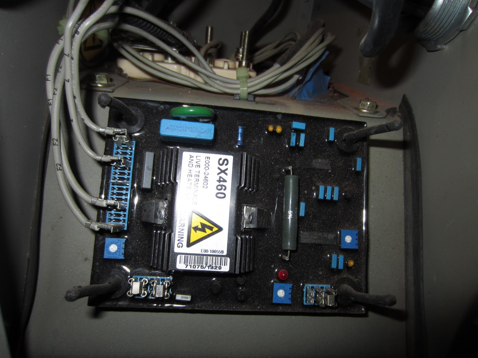 The voltage regulator is held to the chassis by three rubber attachments. We have four control circuits on the left. A voltage potentiometer (POT) on the left under the four control circuits. Another POT at the far right controlling stabilization. Jumpers bottom left and bottom right. What could go wrong?
The four control circuits. I was initially worried I would forget the order in which these go back onto the replacement board. BUT, as it turns out looking closer at the wires, they are LABELLED! Yahoo! One was actually a little loose -- we tightened that one a bit.
I manage to get the old regulator off, but I snapped one of the four rubber attachments. Sliding the new regulator on, it seems to be a snug fit with just three. We can live without the fourth until we can hunt down a replacement.
Jumper check! The old board is pictured above. Bottom left there are two jumpers. The new board only has one. I steal a jumper from the old board. The jumpers are snug buggers. The manual says the bottom right jumper selects voltage frequency (50 or 60 Hz), kinda important. The old board is set correctly. The new board is set for 50 Hz. Move the jumper. No problem. Back to the manual and work with the POTs.
The manual says the POTs are factory set. The voltage regulator and stability POT seem to be set lower than the old board. I figure this is OK. The only warning in the manual is not to OVER voltage your system. Looking at data from early in the generator history we seem to be aiming for about 120V to 128V. So, we begin generator testing!
I start and stop the generator several times. The frequency looks great! Nominal (no load) frequency is suppose to be 60 to 63 Hz. The generator control box confirms frequency stability. Our inverter can indicate bad power from the generator (flashing RED LED). The first start we get 96V (too low). Turn the POT 1/8th turn and we get 102V. Turn it 1/4 and we get pretty close 122V. No RED LED. So, we let it run. Electronics can be fascinating at times. Normally voltage is HIGHER on an open circuit than a closed (loaded) circuit. Our inverter switches from BATT to the generator after a certain period has passed with good power detected from the generator. What surprises me is that the voltage goes UP! Nothing bad happens, but we do hit 132V. So, we shut things down. I turn the POT down and start again. Before the inverter kicks in we sit at about 118V. The inverter seems happy about it. The inverter kicks over and we jump to 127V. Its on the high side, but well within the limits of what we saw previously. I'd rather split the difference a bit over the 120V. Over the charge cycle the voltage does back down from the high side to the low side. We also do a check on the frequency under LOAD: still within 60 to 63 Hz, YES! But, we will see. At times the old board would operate fine and act up.
We hope this fixes our mysterious shutdowns. It isn't fun when you have just 48 hours of stored power if your going to have a good generator run next time. We have a backup plan in progress. We are installing a transfer switch so we can hook up a backup generator to keep things running if our big Kubota really goes down. If that happens, we will have to do things manual. It has been good to have the Kubota operating automatically and reliably for the past two years!
No comments:
Post a Comment